Relay driver dual board schematic circuit circuits electronics lab output gr next Switch & types of switches Relay driver using circuit transistor uln2003 cricuit its microcontrollerslab applications
Switch & Types of Switches - Electromechanical & Electronic
Relay schema mosfet circuits relais electroschematics relays electrique conducteur uln2003 transistor schematic darlington arduino npn bipolaire bascule
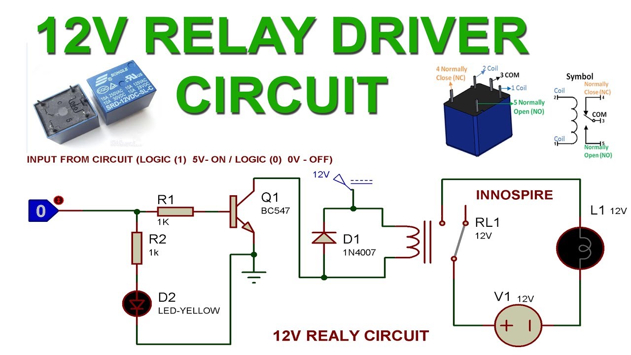
How to make 12v relay driver circuit using transistor
Relay schematicDriving relays with stm32f103 microcontroller using uln2003 relay driver Circuit relay driver drive transistor digital 5v eleccircuit output voltage circuits current example input ma figureRelay driver schematic make control voltage various now will here electronics basic.
4-channel relay driver circuit and pcb designTransistor relay driver circuit in digital 12v, 50a no relayRelay circuit 12v transistor driver using make proteus simulation.

Relay diagram wiring
Relay circuit driver channel pcb module diagram board circuits arduino 5v 12v relays layout ac project isolated operate choose projects4 channel 5v relay module How to make relay driverRelay use diagram wiring diode coil pole voltage through.
Dual relay driver boardPic controlled relay driver Relay circuit driver 555 schematic diagram control circuits seekic electroschematics ic output gr next repositoryRelay driver circuit board dual schematic diagram project electronics lab description circuits.
5 pin relay wiring diagram
555 (tlc555) relay driver circuit4-channel relay driver circuit and pcb design Relay circuit driver channel pcb module diagram board circuits arduino 5v relays 12v layout ac project choose isolated operateHow to make relay driver.
5 pin relay diagram for automotive useHow to make relay driver Optocoupler relay driver with pc817 & 2n3904Vw relay diagram.

Relay channel module 5v schematic control level signal port
Relay driver pic controlled microcontroller circuit circuits using diagram schematic full controller bridge diode diy schematics 12v ac 220v pcbDc relay switch driver circuit Relay opto coupler circuit drive circuits driver diagram darlington through like transistor homemade projects evident operations rest selfSchematic diagram of relay driver..
How to drive a relay through an opto-coupler circuitSimple relay circuit diagram Dual relay driver board circuit schematicRelay driver circuit using uln2003 and its applications.

Relay driver schematic make control electronics basic
Relay circuits schematics .
.


